
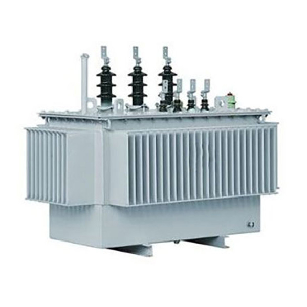
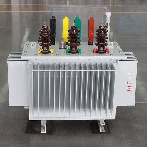
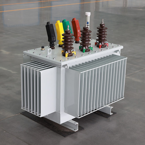
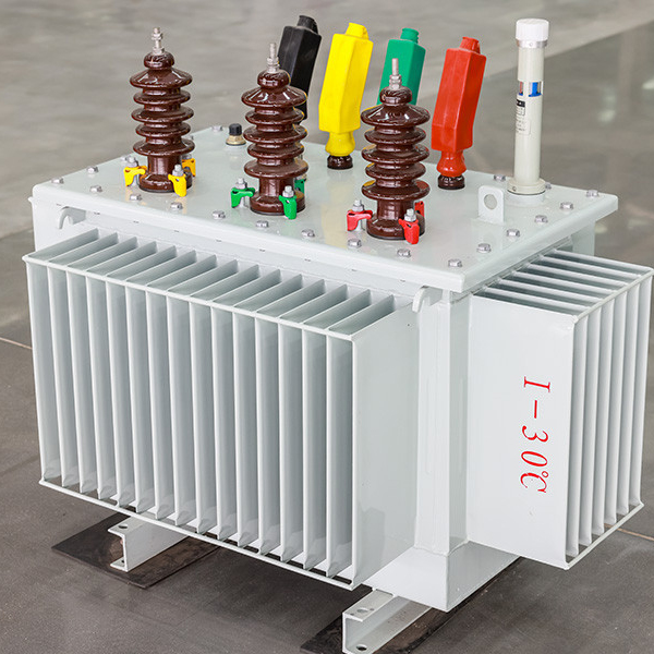
Three Dimensional Wound Core Transformer
Advantages
1.Low loss
The S13-M.RL series of capacity 30-1600kVA no-load loss decreases by 50% on average, and the load loss decreases by 30% on average. S11-M. RL series no-load loss decreased by 30% on average, load loss decreased by 25% on average.
2.Low no-load current
Due to the excellent material of the wound core and the characteristics of the winding process, the no-load current is significantly reduced. S13-M.RL series no-load current decreases by an average of 75% according to the current national GB/T6451-1999. S11-M.RL series no-load current decreases by an average of 75%.
3.Low operating noise
The noise of S13-M.RL and S11-M.RL series is reduced by about 7-9dB according to JB/T10088-1999 noise standard.
4.Strong short circuit resistance
The whole transformer body is in the shape of a body with a triangular prism shape, pull-screws and center are arranged around. It is integrated with upper and lower iron yoke insulation and laminated wood blocks, which can effectively resist the axial and radial mechanical stress during sudden short circuit.
Standards
GB 1094 Power Transformer
GB/T 15164 Oil-immersed power transformer load guide
GB/T 6451 Three-phase oil-immersed power transformer technical parameters and requirements
IEC/60076
Capacity
30kva~10000kva
Voltage
380v~35kv
USES
Distribution transformer
Data Sheet
30 KVA~1000KVA Three dimensional wound core oil immersed distribution transformer | |||||||
Capacity(KVA) |
Voltage combination |
Vector Group Symbol |
NO-load loss ( W ) |
Load loss ( W ) |
NO-load current ( % ) |
||
High pressure ( kV ) |
High pressure tap range ( % ) |
The low pressure ( kV ) |
|
||||
30 KVA |
6 |
±5 |
0.4 |
Dyn11 or Yyn0 |
100 |
630/600 |
0.3 |
50 KVA |
130 |
910/870 |
0.24 |
||||
80 KVA |
180 |
1310/1250 |
0.22 |
||||
100 KVA |
200 |
1580/1500 |
0.21 |
||||
125 KVA |
240 |
1890/1800 |
0.2 |
||||
160 KVA |
280 |
2310/2200 |
0.19 |
||||
200 KVA |
340 |
2730/2600 |
0.18 |
||||
250 KVA |
400 |
3200/3050 |
0.17 |
||||
315 KVA |
480 |
3830/3650 |
0.16 |
||||
400 KVA |
570 |
4520/4300 |
0.16 |
||||
500 KVA |
680 |
5420/4300 |
0.16 |
||||
630 KVA |
810 |
6200 |
0.15 |
||||
800 KVA |
980 |
7500 |
0.15 |
||||
100 KVA |
1150 |
10300 |
0.14 |
||||