
01
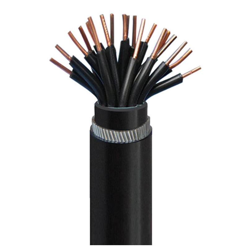
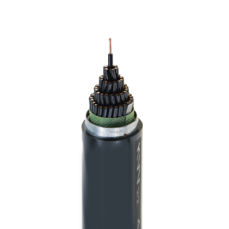
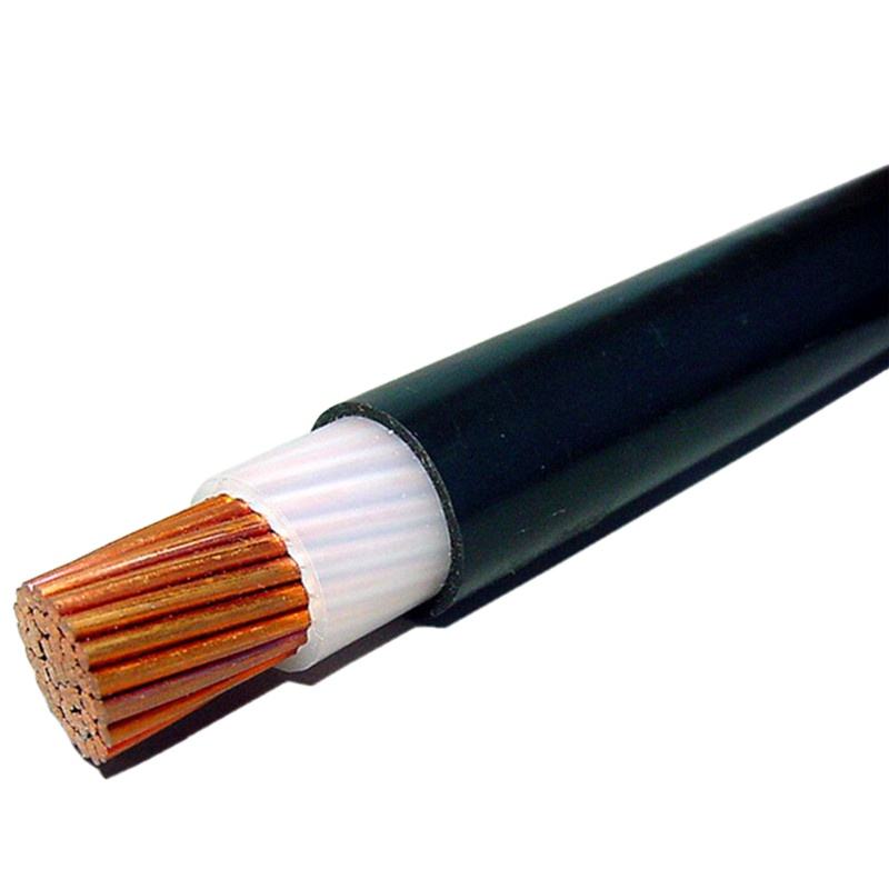
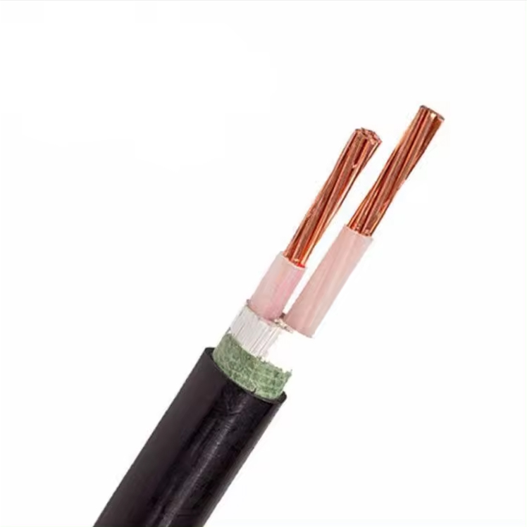
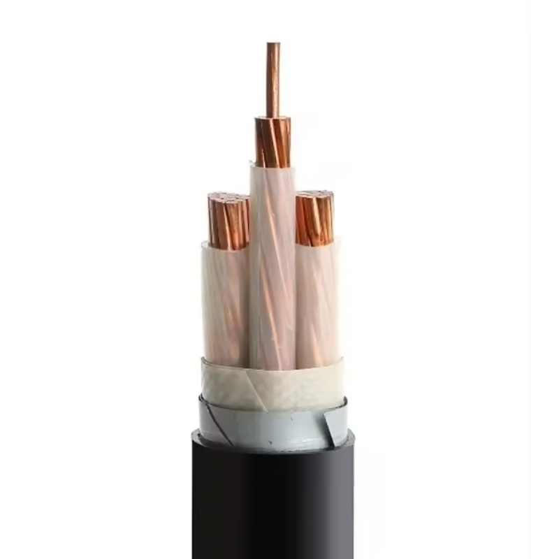
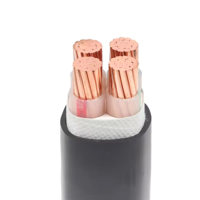
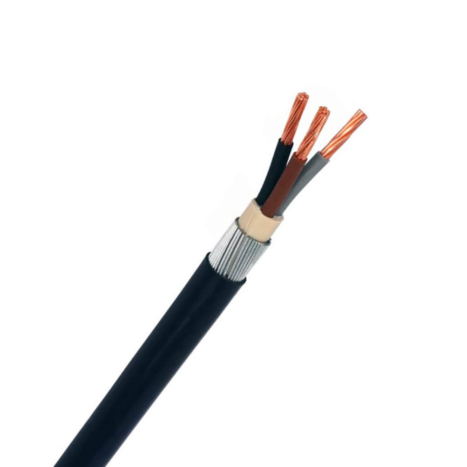
Copper Conductor Armored Control Cable
Application
Laid in fixed places, such as indoors, trenches, tunnels, shafts they can bear huge external mechanical pulling force. They are laid in air, in ducts, in trenches, in steel support brackets or direct in ground, when well protect.
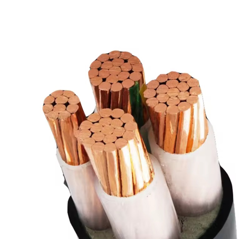
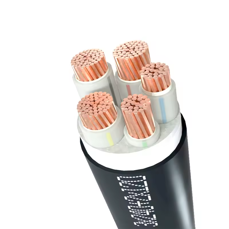
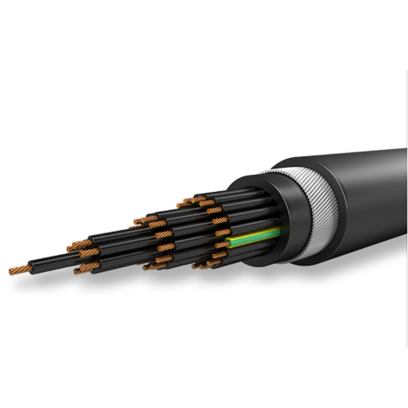
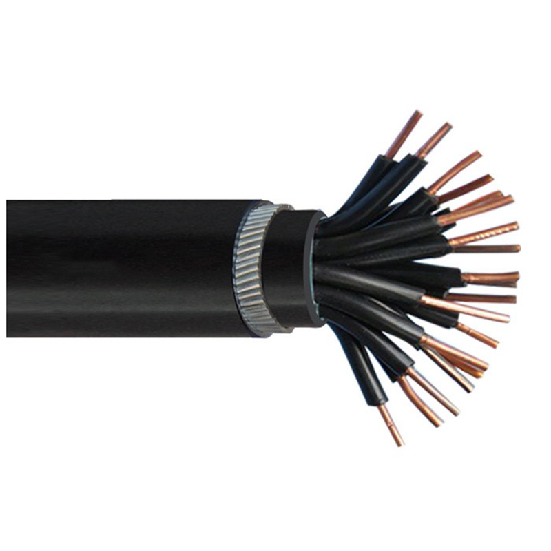
Construction
| Type | KVV32 |
| Name | Copper conductor PVC/PE/XLPE insulated PVC sheathed steel-wire armored control cable |
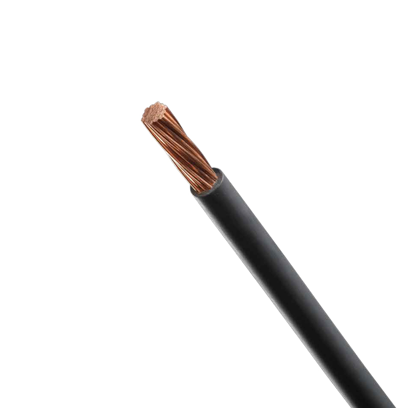
| Conductor material | Copper |
| Conductor construction | Solid or Stranded |
| Insulation material | PVC or XLPE |
| Shield construction | Tinned wire shield with coverage rate (60%-90%) |
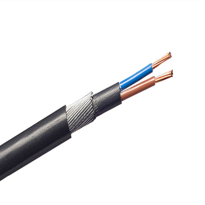
| Armor construction | Steel Wire Armor(SWA)OR Steel Tape Armor(STA) |
| Sheath material | PVC |
Performance Characteristics
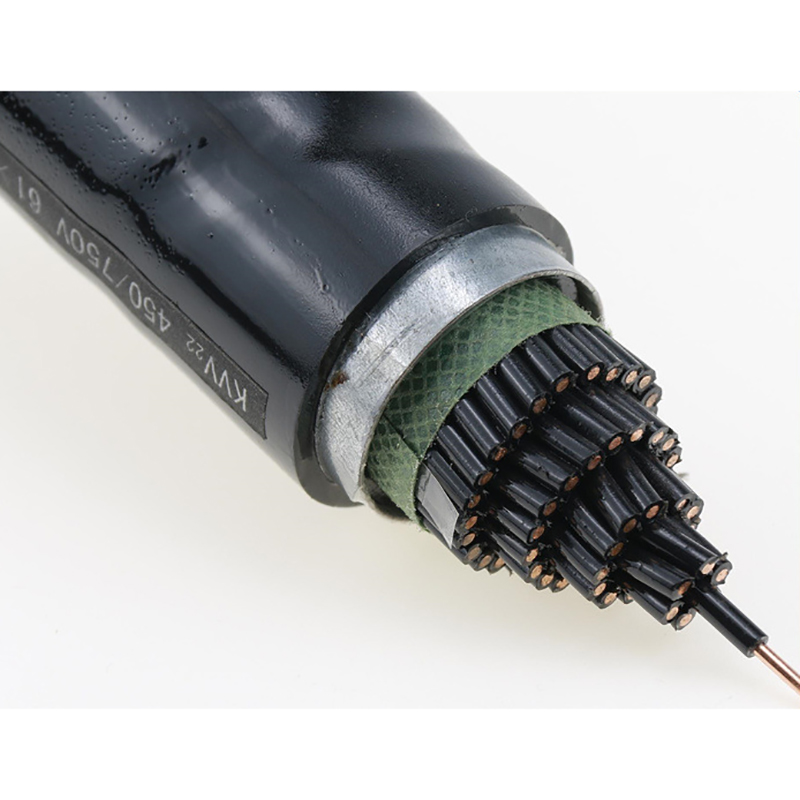
| Standard | IEC-60227 |
| Rated Voltage | 450/750V |
| Conductor | Soft annealed solid copper wire as per class 1 of IEC 228 |
| Insulation | Polyvinylchloride rated 70℃ or 85℃ /Cross-linked polyethylene rated 90℃ |
| Assembly | Cores twisted together to form a round assembly cable with fillers whenever necessary |
| Color code | Black cores with white numbers and one green yellow core |
| Bedding | Polyvinylchloride |
| Armoring | Galvanized steel wire armor to BS 1442 |
| Sheath | Flame retardant polyvinylchloride, black or grey |
| Minimum bending radius | 12 x d (d= overall diameter) |
| Temperature rating | 5 up to 50℃ during operation |
| Working capacitance | Average value 52 ± 2 nF per kilometer. |
Standards
IEC/EN 60502-1IEC 228BS 1442
Data Sheet
| CONDUCTOR SIZE | NUMBER OF CORES | CONDUCTOR | NOMINAL INSULATION THICKNESS | NOMINAL SHEATH THICKNESS | APPROXIMATE OVERALL DIAMETER | APPROXIMATE NET WEIGHT | |
| No.x dia.No. x | Max. DC Res. At 20oC | ||||||
| mm2 | No. | mm | Ohm /Km | mm | mm | mm | Kg/Km |
| 1.5 | 5 | 1×1.38 | 12.1 | 0.7 | 1.5 | 11.8 | 200 |
| 7 | 1×1.38 | 12.1 | 0.7 | 1.5 | 17.38 | 561 | |
| 10 | 1×1.38 | 12.1 | 0.7 | 1.7 | 20.74 | 744 | |
| 12 | 1×1.38 | 12.1 | 0.7 | 1.7 | 19.2 | 501 | |
| 14 | 1×1.38 | 12.1 | 0.7 | 1.7 | 21.97 | 860 | |
| 16 | 1×1.38 | 12.1 | 0.7 | 1.7 | 23.51 | 1052 | |
| 19 | 1×1.38 | 12.1 | 0.7 | 1.7 | 24.4 | 1149 | |
| 24 | 1×1.38 | 12.1 | 0.7 | 1.7 | 27.36 | 1367 | |
| 30 | 1×1.38 | 12.1 | 0.7 | 2 | 29.19 | 1577 | |
| 37 | 1×1.38 | 12.1 | 0.7 | 2 | 31.32 | 1817 | |
| 44 | 1×1.38 | 12.1 | 0.7 | 2.2 | 35.48 | 2327 | |
| 2.5 | 5 | 1×1.78 | 7.41 | 0.8 | 1.7 | 18.73 | 633 |
| 7 | 1×1.78 | 7.41 | 0.8 | 1.7 | 19.82 | 734 | |
| 10 | 1×1.78 | 7.41 | 0.8 | 1.7 | 24.16 | 1089 | |
| 12 | 1×1.78 | 7.41 | 0.8 | 1.7 | 22.02 | 694 | |
| 14 | 1×1.78 | 7.41 | 0.8 | 1.7 | 25.67 | 1273 | |
| 16 | 1×1.78 | 7.41 | 0.8 | 1.7 | 25.49 | 1311 | |
| 19 | 1×1.78 | 7.41 | 0.8 | 1.7 | 26.5 | 1441 | |
| 24 | 1×1.78 | 7.41 | 0.8 | 2 | 30.48 | 1776 | |
| 30 | 1×1.78 | 7.41 | 0.8 | 2 | 32.28 | 2054 | |
| 37 | 1×1.78 | 7.41 | 0.8 | 2 | 35.46 | 2579 | |
| 44 | 1×1.78 | 7.41 | 0.8 | 2.2 | 38.84 | 2999 | |
| 4 | 5 | 1×2.26 | 4.61 | 0.8 | 1.7 | 19.3 | 727 |
| 7 | 1×2.26 | 4.61 | 0.8 | 1.7 | 20.45 | 855 | |
| 10 | 1×2.26 | 4.61 | 0.8 | 1.7 | 25 | 1267 | |
| 12 | 1×2.26 | 4.61 | 0.8 | 1.7 | 22.89 | 871 | |
| 14 | 1×2.26 | 4.61 | 0.8 | 1.7 | 26.59 | 1505 | |
| 16 | 1×2.26 | 4.61 | 0.8 | 1.7 | 27.7 | 1639 | |
| 19 | 1×2.26 | 4.61 | 0.8 | 2 | 29.45 | 1853 | |
| 24 | 1×2.26 | 4.61 | 0.8 | 2 | 33.7 | 2310 | |
| 30 | 1×2.26 | 4.61 | 0.8 | 2 | 36.49 | 2885 | |
| 37 | 1×2.26 | 4.61 | 0.8 | 2.2 | 38.75 | 3323 | |